Window Layout
The image below shows the main Realtime Landscaping workspace, with each area of the interface labeled. The example shown is Realtime Landscaping Architect; Plus and Pro are very similar.
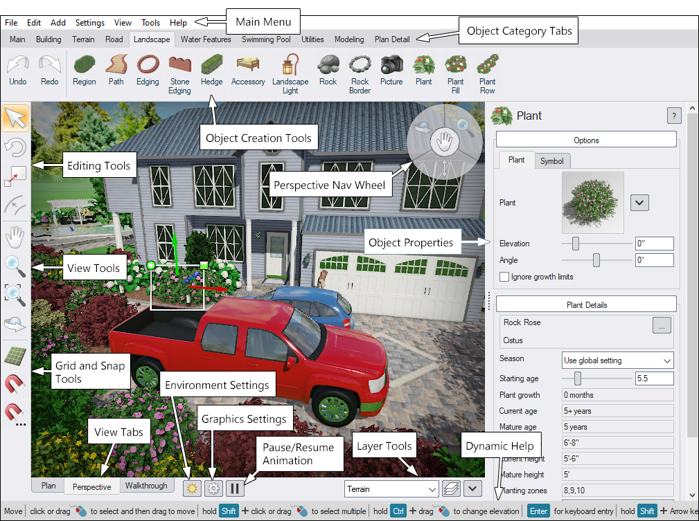
1. Main Menu, Object Category Tabs, and Object Creation Tools
This area contains the commands you use to open, save, print, edit, and build your design.
Main Menu
The Menu Bar (File, Edit, Tools, etc.) provides access to common commands such as opening and saving files, importing, printing, undo/redo, and application settings.
Many menu commands also have keyboard shortcuts. When a shortcut is available, it appears to the right of the command in the menu (for example, Ctrl+C for Copy).
Object Category Tabs
Objects you can add to a design are organized under Object Category tabs. Click a tab to show the related tools and object buttons.
- Main - Common commands such as Save, Copy, Paste, and Print.
- Building - Construction and hardscape objects such as Houses, Patios, Retaining Walls, and Fences.
- Terrain - Tools for shaping and grading terrain (Slope, Area Grader, etc.).
- Road (Architect) - Road and streetscape tools (roads, sidewalks, curbing, signs, and more).
- Landscape - Core landscaping objects such as Plants, Regions, Paths, and Edging.
- Water Features (Pro, Architect) - Ponds, irrigation, fountains, and related water elements.
- Swimming Pool (Pro, Architect) - Pool shapes and pool accessories.
- Utilities - Helper objects such as Text, Overlays, and Lot Boundaries.
- Modeling - Tools for creating or editing custom models and accessories.
- Plan Detail (Architect) - 2D-only objects that appear in Plan view (Symbols, Plant Legends, and more).
Object Creation Tools
To add an object:
- Click the Object Category tab that contains the object.
- Click the object's button.
- Follow the on-screen instructions shown in the Dynamic Help area at the bottom of the screen.
Tip: If you're unsure what a button does, hover over it to see a short description. For detailed help, click the tool and press F1.
See Adding Objects for more information.
2. Viewport
The viewport is the main workspace where your design is displayed and edited. It acts like a virtual camera looking at your project, showing the terrain, structures, plants, and other objects in your scene.
In the viewport you can:
- Select objects by clicking them (or drag a selection box to select multiple items).
- Edit objects interactively by moving, rotating, or resizing them with the mouse (depending on the active tool).
- Change appearance and settings using the Property Window, where you can adjust materials, dimensions, elevation, and other object-specific options.
- Navigate the view by panning, zooming, and rotating the camera to inspect your design from any angle.
The viewport's display and navigation controls depend on the current viewing mode. Choose the mode that best fits what you're doing:
- Plan — a straight-down view for accurate placement and layout.
- Perspective — a 3D view for evaluating depth, scale, and overall appearance.
- Realtime Walkthrough — an interactive first-person view for exploring the design as if you were walking through it.
3. Object Properties
The Property Window appears on the right side of the screen when you select an object. Use it to view and edit the selected object's settings — for example, choosing a different plant, changing a material, adjusting elevation, or modifying object-specific options (such as a sprinkler's spray angle).
For more information, see Setting Object Properties.
4. Dynamic Help
The Dynamic Help area (at the bottom of the screen) provides step-by-step instructions for the tool you are currently using. This is especially helpful when you are learning the program because it shows the exact actions and modifier keys available for the current operation.
Example: When adding plants, Dynamic Help may explain how to hold Ctrl to place multiple copies without reselecting the tool.
5. Layer Tools
Layers help you organize your design and control groups of objects. For example, you might place irrigation objects in one layer and plants in another, then hide or lock layers as needed while you work.
Layers are also useful for presentations: you can put alternate design ideas in separate layers and quickly show/hide them to compare options.
Important: When working with multiple layers, pay attention to the current layer, because new objects are added to the currently selected layer.
For more information, see Using Layers.
6. Environment, Graphics, and Animation Buttons
These buttons provide quick access to global scene and display options:
 Click to open the Environment Settings dialog (time of day, sky, weather, season, and more). Shortcut: F3.
 Click to open the Graphics Settings dialog (options that affect the appearance and performance of the scene in Perspective view). Shortcut: F7.
 Click to pause or resume animations (water, fire, smoke, and other animated effects). Shortcut: Pause.
7. View Tabs
Use these tabs to switch how you view your design:
-
Plan View
A 2D view that is ideal for accurate placement and editing. In Architect, many objects can be styled specifically for Plan view, and Plan Detail objects only appear here. -
Perspective View
A fully 3D view for evaluating height, depth, and overall realism. This view is especially useful for setting elevations, sculpting terrain, and placing objects accurately in 3D space. -
Realtime Walkthrough
A first-person walkthrough mode for exploring the design as if you were on-site. Walkthrough includes special animations and sound effects. You cannot edit the design in this view.
See also: Plan View, Perspective View, and Realtime Walkthrough.
8. Perspective Nav Wheel
The Navigation Wheel provides quick shortcuts for changing your viewpoint in Perspective view (such as orbiting, panning, and zooming). It's optional — use it if you like this style of navigation.
See Adjusting the View for details.
9. Edit, View, and Snap Grid Tools
These tools control how you select/edit objects, how you move around the design, and how snapping behaves.
Edit Tools
Edit tools are used to select, move, rotate, and scale objects. When working with shape-based objects (such as edging, paths, and fill regions), these tools can also be used to edit the points that define the shape.
View Tools
View tools control the camera in both Plan and Perspective views. For example, Orbit rotates the camera around the scene, and Zoom moves the view closer or farther away.
See Adjusting the View for more information.
Snap Grid Tools
Grid tools let you show/hide grid lines, enable/disable snapping, and customize snap behavior.
Grid lines are for reference only and can be turned on or off at any time. Snap settings are independent of whether grid lines are visible (you can have one enabled without the other).
See Snap Settings for details.
10. Object List
The Object List helps you manage and find items in your design — especially in large projects. It provides a structured list that you can use to:
- Quickly locate objects without hunting for them in the viewport.
- Select objects from a list (selection stays synchronized with the viewport).
- Show/hide or lock/unlock groups of objects to simplify editing.
The Object List can be displayed in two ways: by Layer or by Type.
 Show objects by layer
In this mode, the Object List shows each layer in your design. Click the arrow next to a layer name to expand it and view the objects inside that layer.
Next to each layer are two controls:
- Hide (visibility) - Hides/shows all objects in the layer.
- Lock (selectability) - Locks/unlocks all objects in the layer to prevent accidental selection or editing.
Some layers may appear partially hidden or partially locked. A mixed/gray state indicates that only some objects inside the layer are hidden or locked.
Selecting from the list: - Click an object name to select it. - Ctrl-click to add/remove individual objects from the selection. - Shift-click to select a range of objects.
To add, delete, or rename layers, use the Edit Layers dialog. (Unlike the Object List, that dialog focuses on layer management rather than showing every object inside each layer.)
 Show objects by type
In this mode, objects are grouped by their type (for example: Plant, Patio, Pool Decking, and so on). The hide/lock controls work the same way — but they affect every object of that type in the design.
Tip: When an object (or group of objects) is hidden or locked, it cannot be selected, edited, or deleted until it is shown/unlocked again.
You can also hide or lock objects by type using the Show/Hide Objects dialog. (Unlike the Object List, that dialog does not list each individual object.)
Print Margins (Architect) (not shown)
In Plan View, dashed margin lines indicate the printable area for the currently selected printer. Items outside this border may be clipped when printed. If you change printers or page settings, the printable area may change as well.