Setting Object Properties
When an object in Realtime Landscaping is selected, a property dialog will appear to the right of the screen. Object properties can be modified to change such attributes as size, shape, material, elevation, and more. The types of properties available depend on the object.
Property changes are easy to make, and they can be quickly undone if needed; so feel free to experiment.
Common Properties
Some common properties that are used by many objects are shown below.
| Object Title | |
|---|---|
| Object Layer | Click to move the object to a different layer. |
| Help and Property Options | Click to open a menu with help and property-related options (shown below). |
| Object Properties Menu | |
|---|---|
| Help | Open the user guide for the selected object. |
| Copy Properties | Copy the object's properties to the clipboard. |
| Paste Properties | Paste the copied properties onto the selected object. |
| Copy Properties | Copy the object properties to the clipboard. |
| Save Default Properties | Save the selected object's current properties as the default for new objects of this type in this and future designs. |
| Reset Default Properties | Restore the default properties for this object type. This affects new objects only. |
| Advanced Object Properties | Edit advanced options for the selected object. |
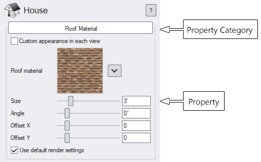
| Material | |
|---|---|
| Material image | Click the image to select a different material |
| Custom appearance in each view (Architect) | In Realtime Landscaping Architect, this allows you to customize the appearance of the object in the Perspective and Plan views. |
 |
Click the drop-down arrow next to the image for additional options for editing the material. |
| Size | Size of the material in feet or meters. |
| Angle | Material rotation angle in degrees. |
| Offset X | Amount to shift the material in the horizontal direction. |
| Offset Y | Amount to shift the material in the vertical direction. |
| Use default render settings | Use the default metallic, smoothness, glow, and other settings for the material. Uncheck this option to set your own values. |
| Metallic | How metallic the material is. This is typically 0 for non-metallic and 100 for fully metallic. This affects the appearance of the material, not what's underneath it. For example, car paint would typically use a Metallic value of 0 because the paint has non-metallic reflection properties. |
| Smoothness | How smooth the material is. Use 0 for a rough (matte) surface such as concrete. Use 100 for a completely smooth surface such as car paint. |
| Transparency | Makes the surface semi-transparent. This option is only available on some objects. |
| Glow | Makes the surface self-illuminating. This option is only available on some objects. |
| Displacement | Sets the strength of the displacement (height) effect (described below). |
| Hide tiling pattern | Reduces visible repetition in tiled textures (described below). |
| Size and Rotation | |
|---|---|
| Width | Width of the object. |
| Depth | Length of the object. |
| Height | Height of the object. |
| Rotate about X | Rotation angle of the object about its X axis. If your view is facing north, this will rotate the object forward or backward. |
| Rotate about Y | Rotation angle of the object about its Y axis. If your view is facing north, this will rotate the object left or right as if it were sitting upon a pottery wheel. |
| Rotate about Z | Rotation angle of the object about its Z axis. If your view is facing north, this will rotate the object left or right as if it were sitting upon the face of a clock. |
| Align to terrain | Tilt the object to align it to uneven terrain. Uncheck this option to keep the object upright. |
| Snap to surface | Align the object to non-flat surfaces such as house walls, retaining walls, and other objects (excluding some objects such as accessories). |
| Scale evenly | When one dimension of the size is changed, adjust the other sizes proportionally. Uncheck this option to change one dimension without changing the others. |
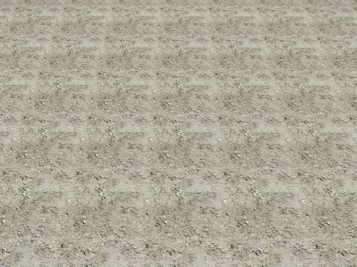
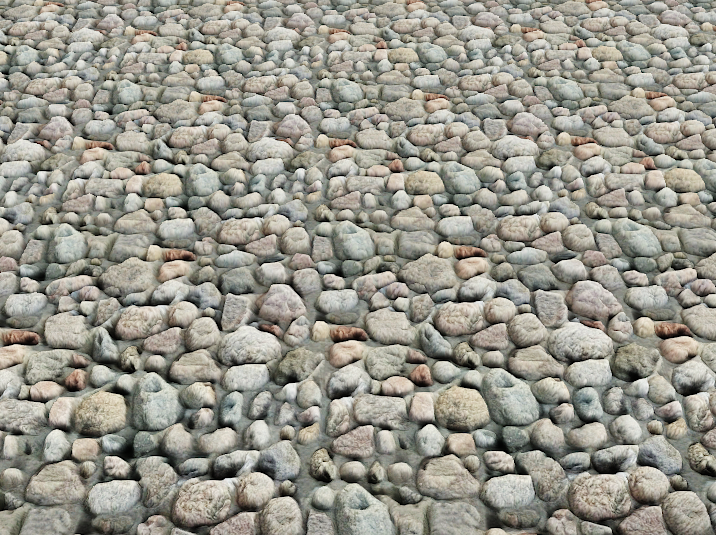
Hide Tiling Pattern
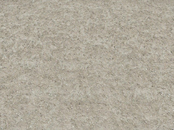
The Hide tiling pattern option reduces visible repetition in textures that tile across large areas. At a distance, the software subtly varies the texture so the surface looks more natural and less "stamped."
This is most effective for organic materials where repetition is easy to spot, such as grass, mulch, soil, gravel, and natural stone. It is typically less helpful for highly regular patterns - such as brick, tile, or pavers - where straight grout lines and repeating geometry remain visually obvious.
Hide Tiling Pattern Off
Hide Tiling Pattern On
Displacement Mapping
Displacement mapping (also known as Height Mapping) causes parts of the surface to appear raised or recessed. This can add depth to textures such as stone, brick, and wood.
Use the Displacement setting to control the strength of the effect:
-
Low values add subtle relief and usually look the most realistic.
-
High values can exaggerate the surface and may look unnatural, especially on smooth or finely detailed textures.
Note: Displacement mapping only affects the appearance of the surface, but does not change the actual shape or silhouette of objects.
Displacement Mapping Off
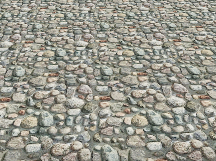
Displacement Mapping On
Symbol Options
Applies to:  Plus Pro
  Architect
By default, the Plan view shows a top-down representation of the object. You can change how it appears in the Plan view, or replace it entirely with a symbol from the symbol library.
- Select the object.
- Click the Symbol tab.
- Choose a Symbol Type (shown below).
-
Adjust the Symbol Options for the desired appearance.
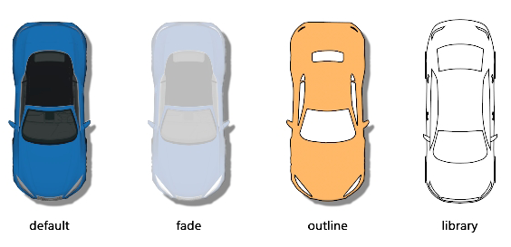
| Symbol Type | |
|---|---|
| Symbol Type | Determines how the object appears in the Plan view. Use Default for a top-down view of the object. |
The following options appear when Symbol Type is set to Fade.
| Fade Options | |
|---|---|
| Fade amount | Controls how faded the object appears in the Plan view. |
The following options appear when Symbol Type is set to Outline.
| Outline Options | |
|---|---|
| Material | Select the material used to fill the symbol in the Plan view. This is optional. If you only want the symbol outline, set the Transparency to 100 (see below). |
| Size | Adjusts the material size. |
| Angle | Rotate the material. |
| Offset X,Y | Shift the material left/right or up/down. |
| Transparency | Make the material partially or fully transparent. |
| Line Style | Edit the outline Line Style. |
| Extract Shapes | Create one or more Shape objects from the Plan view outline. The extracted shapes are separate objects and are not linked to the original object. Use them to customize the outline or create a new symbol with the Symbol Creation Wizard. |
The following options appear when Symbol Type is set to Library.
| Library Options | |
|---|---|
| Symbol | Click to select the desired symbol. |
| Width | Set the symbol width. This option is disabled if Use model size and angle is checked. |
| Height | Set the symbol height. This option is disabled if Use model size and angle is checked. |
| Angle | Set the symbol rotation angle. This option is disabled if Use model size and angle is checked. |
| Offset X,Y | Shift the symbol left/right or up/down. This is helpful when the symbol does not align with the object. |
| Transparency | Make the symbol semi-transparent. |
| Scale evenly | When one dimension of the size is changed, adjust the other sizes proportionally. Uncheck to change one dimension without changing the others. |
| Use model size and angle | Automatically applies the object's size and rotation to the symbol. Uncheck to enter custom Width, Height, and Angle values. |