Adding a Loft

The Loft tool allows you to create a shape that is extruded along a path. You can vary the size of the shape along the path, add bends and curves, and adjust the elevation of each path point.
Use the Loft tool for creating custom slides, custom pipes and tubing, curved boards and arches, and much more.
The object consists of two parts -- the shape and the path. The shape is always flat on the ground (to make it easier to edit), while the path can be placed anywhere and can be any 3-dimensional shape.
To add a Loft:
- From the Modeling tab, click Add Loft.
- Draw the outline of the desired shape by clicking the left mouse button to add points. Press the Backspace key to remove the last point added, and press the Esc key to cancel.
- To finish drawing the shape, place the last point on top of the first point. Or right-click to place the last point.
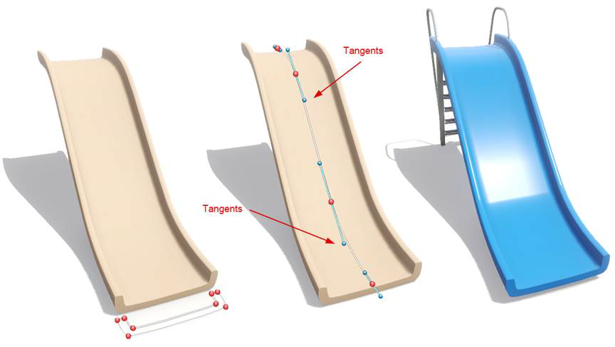
Below is an example of a slide created using the Loft object. The picture on the left shows the shape that will be lofted. The picture in the middle shows the loft path. (Notice how the tangent handles can be adjusted to give you more control over the shape.) The picture on the right is the completed object with the final material. The ladder and handles were added by converting an existing slide to a Custom Model and removing the unneeded polygons.
Editing the Loft Path
When you add the loft object, a simple path consisting of two points will be created. You can edit the path as desired, including inserting points, making the corners sharp or curved, and so forth.
To edit the path:
- Click Edit Points in the Path group.
- Edit the path points as desired. See Editing Points for details.
- To adjust the path height, select the desired point(s) and enter the height using the Height property. Or drag the green vertical arrow to set the height using the mouse.
- When you are finished editing the path, click Edit Points again to leave point editing mode.
Adjusting the Bank Angle
The bank angle is calculated automatically based on the path curvature. You can adjust this angle by changing the elevation of the Bezier curve handles (the blue points).
To adjust the bank angle:
- Click Edit Points in the Path group.
- Select the point you want to adjust by clicking on it.
- If the Curve type is not Bezier or Bezier Corner, choose one of these by clicking the corresponding button in the Path group.
- Press and hold the Ctrl key while using the mouse to click and drag the blue Bezier handles to adjust their elevation (and indirectly, the bank angle).
- When you are finished editing the path, click Edit Points again to leave point editing mode.
Editing the Loft Shape
You can edit the loft's shape at any time. The shape can be open or closed, and can even contain holes (see Using Booleans to create Complex Shapes ).
Since the loft position and extrusion direction are determined by the path, the position of the shape itself is irrelevant.
To edit the shape:
- Click the Edit Points button in the Options group.
- Edit the path points as desired. See Editing Points for details.
Tips:
- The shape of a loft can be edited after it is created by clicking the Edit Points button. See Editing Points for details.
- When you are finished creating the object and don't plan to make any more changes to its shape, you can convert it to a Custom Model for more control over its size and orientation. However, once you do this, you will no longer be able to edit the underlying shape, so we recommend saving a copy first.
- If a loft has a closed shape, then caps will be added to the top and bottom (see picture above). If a loft has an open shape, then caps will not be added.