Adding a Contour Line
Applies to:  Plus Pro
  Architect

The Contour Line object is used to create free-form lines that represent a fixed height. Using contour lines is an efficient way to control the topography of your landscape design. Both open and closed contour lines are supported.
To add a Contour Line:
- From the Terrain tab, click Add Contour Line.
- Draw the contour line by clicking the left mouse button to add points. Press the Backspace key to remove the last point added, or press the Esc key to cancel. If you would like to input the distance and angle manually, place at least one point and then press Enter.
- To finish drawing the contour line, connect the last point to the first point or right-click to place the last point.
- Set Elevation to the desired height. Use a positive number to raise the terrain, or a negative number to lower the terrain.
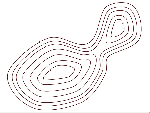
The following is a set of contour lines in the Plan view.
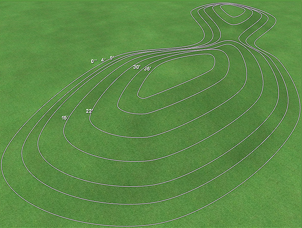
Here are the same contour lines in the Perspective view.
Tips:
- You can import contour lines from DWG and DXF files. See CAD Import Wizard for details.
- Contour lines should not overlap. (If they do, a dimple will appear in the terrain.)
- Closed contour lines can be used to quickly create terraces.
- Multiple contour lines can be used in a single landscape design.
- Contour lines can be any shape and size.